Thursday 12 January 2017

Vessel Pressure Testing

The Vessel Pressure Testing article provides you with information about pressure vessel hydro-static testing requirements and related item in pressure vessel inspection.

The requirements have been described based on ASME Code Section VIII. You need to do this test after completion of the construction process, but before the internal parts assembly and also before painting process.

This content covers all major requirements and provides you with guidelines for test performance.

Please note that performing the pneumatic test instead of the Hydro-Static Test is not allowed, and it can be replaced only when it is not possible due to the design and process.

Vessel pressure testing requirements have been addressed in UG-99 and UG-100 in ASME Code Section VIII Div. 1.

These are important points, which you need to take care of in vessel pressure testing:

Activities before pressure vessel hydro-static testing, which need to be checked by the manufacturer quality control team and a third party inspector:

1. Checking all welding already finished and fully accepted by the NDT examination per the project Inspection and test plan.

2. Making sure the inner part of the vessel is clean and free of remaining slag or other elements. making sure the external surface is dry for the correct execution of the visual inspection during the vessel pressure testing.

3. Checking the pressure gauges' calibration tag and certificate and the range of the lower limit and upper limit of the gauges. It needs to be between 1.5 and 4 of the pressure test value.

4. Controlling testing equipment such as the test pump and housing for soundness and tightness.

5. Making sure the test temperature will not violate the following values: 
Min. Test temperature= MDMT + 30°F
Max. Test temperature = 120°F
MDMT is the pressure vessel minimum design metal temperature, and it is stated in the pressure vessel design document.
This reduces the risk of a brittle fracture during the test.

6. Making sure which reinforcement pads are already soap tested.

7. Controlling the testing water quality and using corrosion inhibitor if it is necessary or when the vessel metal is sensitive material

8. Checking of vents. It is required to be placed at high points of the vessel in a position where it is possible to purge air pockets while the vessel is filling.

Activities during the pressure vessel hydro-static testing that need to be checked by the manufacturer quality control team and a third party inspector:

1. Making sure the filling and pressurizing are done from the lowest point and venting from the highest point.

2. Witnessing water overflow through the venting in order to assure that no air bubbles remain in the vessel.

3. Controlling and witnessing which pressurizing is done in three stages as follow:

First Stage: Raise the pressure to 40% of the final pressure, stop pressurizing, keep it for 5 minutes, and then make a fast visual inspection of the external surface.

Second Stage: Restart pressurizing up to 70% of final pressure, stop the operation, keep for 5 minutes and make a fast visual inspection on external surface.

Third Stage: Restart pressurizing up to 100% of the final pressure, stop the operation, and keep for 45 minutes.

4. When 45 minutes elapse, making sure the de-pressurizing is started and the pressure is dropped to the “Inspection Pressure.”

This inspection pressure can be calculated as following:

Inspection Pressure = Hydrostatic Test Pressure / 1.3
Making sure a detail and a comprehensive inspection is carried out over the whole body of the vessel and in the welding joints and attachments.

5. Making sure the pressure vessel hydro-static testing pressure calculated correctly as following:

Hydrostatic Test Pressure = 1.3 x MAWP X Stress ratio

Stress Ratio = (Allowable Stress at Test Temperature)/(Allowable Stress at Design Temperature)

6. Making sure the vessel is immediately and carefully drained after the test and dried by air.

Activities after the pressure vessel hydro-static testing that need to be checked by the manufacturer quality control team and a third party inspector:

1. The pressure vessel hydro-static testing report needs to be prepared by the manufacturer quality control team and signed by the third party or authorized inspector.

2. If the test failed by leaking from weld joints or any other kind of defect, it is necessary that the vessel is drained and dried and repaired based on approved repair procedure. pressure vessel hydro-static testing needs to be repeated.


Wednesday 4 January 2017

Maintenance of Glass-Lined Equipment

Glass-lined steel equipment is used in a wide range of chemical processes that involve harsh chemicals, including the production of pharmaceuticals, specialty chemicals, agricultural products and polymers. One of the reasons for the attraction is that glass is resistant to attack from most chemicals and to mixtures of corrosive materials. In addition, it has a smooth, anti-stick surface, is easy to clean, and does not introduce impurities to the process materials.

The metals that compete with glass for corrosion resistance are tantalum, titanium and zirconium, all of which are several times more expensive than glass-lined steel. Glass-lined steel can be used with most acid or alkaline media, since glass withstands attack from most substances in both oxidizing and reducing environments. The exceptions include fluorides at any temperature or concentration; hot, concentrated phosphoric acid; and highly alkaline chemicals at elevated temperatures.

Glass-lined vessels typically consist of a carbon-steel body with a bonded inner lining of specially formulated glass. The glass is composed of several oxides and silicates. It is blended and heated to the melting point, emptied through a chute, quickly cooled and solidified into particles called frit. The first coat of glass applied  to the steel is the ground coat; it has limited corrosion resistance and is used solely to develop a chemical bond with the base metal. After the ground coat is cooled, the chemically resistant glass is applied. This procedure is repeated until a desired glass thickness is achieved, which is usually 40–90 mils.

Equipment that is often supplied with a glass lining includes reactors, storage tanks, columns, dryers and filters, as well as pipes, valves and fittings. The internal components of the vessels, such as agitators, baffles and dip pipes, are also supplied with glass coatings. In general, glass-lined vessels are designed to operate at temperatures up to 500°F (260°C) and pressures of 130–150 psig (9.14–10.55 kg/cm2), although they can be built to withstand much higher pressures.

The leading cause of problems in the operation of glass-lined equipment is mechanical damage resulting from impact, and the second is thermal shock, caused by heating or cooling a vessel too quickly. These and other problems can be avoided or minimized by proper operation of the equipment and by educating personnel in the procedures for working with glass-lined equipment.

Preventive maintenance

The key to a long, healthy life for glass-lined equipment is an inspection and maintenance program that is designed for early detection of damage. A small chip or pinhole, if not repaired immediately, can lead to corrosion of the steel substrate and could result in major harm to the equipment. The inspection process starts with a thorough review upon delivery of the glass-lined equipment to the plant to ensure it was not damaged in transit. Thereafter, the equipment should be inspected at regular maintenance intervals ranging from several times a year, to once every two years, depending on the severity of service. More-frequent or even continuous testing may be conducted if the operating conditions are especially severe, or if damage is suspected.

A typical maintenance checklist for glass-lined equipment should nclude: visual inspection of the lining; spark testing for signs of glass-lining failure; glass-thickness readings; inspection of tantalum repair plugs and patches, if installed; vessel nozzle connections; and vessel jacket connections. As in conventional equipment, the list should also include motor and drive performance and the mechanical seal and lubricator (if applicable).

Spark testing. Glass linings should be electrically tested after installation and at regular maintenance intervals in order to detect small defects before they become more serious problems. A spark test can be performed with either d.c. or a.c. spark testers, which apply approximately 6,000 V at very low amperage. In either case, the spark tester consists of a hand-held brush that is connected via a cable to a portable detector. The inspector carefully brushes the glass surface, using a semi-circular motion, until the entire surface has been covered. If the brush encounters so much as a pinhole, current flows to the steel shell and arcing occurs.

Incidentally, d.c. spark testers are the preferred way to check vessel linings because they are grounded to the steel structure. The a.c. types, which are connected to a power outlet, are generally used for checking components that are completely encapsulated in glass, such as agitator blades, where grounding is not possible.

Also available are permanent d.c. systems that are installed in a vessel and monitor the integrity of the glass lining continuously while the vessel is in service. A conductive glass electrode is mounted on an internal accessory, such as a flush valve at the bottom of the vessel, and the other end of the circuit is connected to the outside of the grounded steel shell. If there is a leak in the glass, a current of a few milliamps flows between the electrodes via the conductive liquid contents of the vessel and activates audible and visual alarms. Besides continuous monitoring, an online system avoids the need for someone to enter the vessel to conduct an inspection.

Another option is to use a portable instrument that is based on the same principle. In this case, the vessel is filled with a conductive liquid, and a probe is suspended in the liquid on a cable. Although monitoring is not continuous, the test can be done as often as considered necessary, and the probe can be used in multiple vessels. With either system, the approximate location of a leak can be determined by filling or draining a vessel until the alarm is activated or deactivated.

Monitoring glass thickness. Another inspection task that is done electrically is measurement of the glass thickness, a calculation that is critical to the life of a vessel. It is performed with a handheld magnetic induction or eddy-current type instrument that comprises a probe on a cable. When the probe is touched to the surface of the glass, it sends out a current that is reflected from the steel backing of the vessel. The time taken to receive the feedback signal indicates the glass thickness with an accuracy of at least ±5%. This value is displayed on the instrument. To conduct these tests, the vessel should be mapped in a grid pattern, with readings taken at intervals of 24 –36 in. (61–91.5 cm).

The appropriate interval between glass-thickness measurements depends on a number of factors. If the reactants used in a process are very aggressive, it may be wise to measure the thickness of the reactor’s glass lining every three to six months. The frequency of inspections should increase as the vessel ages. Areas that exhibit a loss of fire polish (the smooth finish achieved in the glass furnace) should be more thoroughly inspected and monitored. In particular, agitator blades and baffles are more likely to show signs of wear and should be tested more frequently than other areas.

It is good practice to maintain a logbook for each vessel, indicating the date of installation and the dates and results of spark tests, visual inspections and glass-thickness tests. The log will help maintenance personnel to determine the estimated service life of the equipment and could help prevent a vessel failure. It is advisable to  call the equipment manufacturer when the thickness of the glass lining thins to about 0.03 in. (0.08 cm), as it is probably time to take the vessel back to the factory for reglassing. A reglassed vessel can carry the same glass -lining warranty as a new vessel.

Before sending a vessel to the manufacturer for repair and reglassing, it is necessary to clean the vessel and jacket thoroughly, removing all chemicals and heat-transfer fluids. Insulation should also be removed, as well as all accessories not subject to repair or replacement. These may include the agitation system, clamps, split flanges, pipes, valves and fittings. Any plugs or patches should also be removed, as product may have become trapped behind them.

Field repairs

Reglassing, however, is the remedy of last resort and should not be necessary until the lining has been worn thin by years of service or has been severely damaged. Such areas can be repaired economically by means of a plug or patch made of tantalum, which is used because of its corrosion resistance. Plugs are designed to repair small holes, up to 4 in. (10 cm) dia., whereas patches are intended for larger areas of damage. Old repair plugs and patches should be checked during an inspection. Loose plugs and patches should be replaced, not retightened.

A tantalum repair plug consists of a stud, nut, disc and a gasket of polytetrafluoroethylene (PTFE, or Teflon). It can be used to repair defects by the following procedure:

• Clean the area to be repaired

• Remove the damaged glass

• Choose the appropriate size plug

• Drill and tap to the appropriate dimensions

• Screw in the stud; ensure that the hole is perpendicular after the plug is installed; ensure that the gasket is sealed properly

• Apply a cement into the cavity

• Install the PTFE gasket

• Install the disc

• Screw on the nut

Upon drilling a hole, prevent the tip of the drill from slipping over the glass by turning the chuck by hand and applying pressure, such that the tip cuts its way through the lining.

Be sure to mill at slow speed and in short bursts to avoid chipping the glass around the periphery of the hole. Complete the drilling process by using a ball mill or conical mill. Prior to installing the patch, a filler, such as furan or silicate, is injected into the damaged area. In the case of larger holes, a sheet of tantalum, with a PTFE gasket, is placed across the damaged area and is fastened into place using tantalum studs and nuts around its periphery.

This repair system can also be employed to restore damaged glass around a nozzle, which is glassed on its interior and on the nozzle face. If the steel has been damaged, the affected area may be filled with titanium putty or furan, and a tantalum sleeve may be installed inside the nozzle. A solution that is less expensive than tantalum for repairing glass around nozzles is the use of a repair sleeve made of PTFE. In this approach, titanium putty may be used to fill the damaged area. Then, a layer of cement is added, and the PTFE sleeve is installed on top of the cement to form a seal.

Causes of glass failure

There are many reasons for glass failure in glass-lined steel equipment. Most may be avoided by following the correct procedures when working with the equipment. For example, mechanical shock, which accounts for approximately 75% of all failures, is often the result of human error.

Mechanical shock and chemical attack. A common cause of glass failure from mechanical shock is objects falling on or against the outside or inside of a vessel. A sharp blow on the outside can cause the glass to “pop off,” depending on the severity of the blow. If mechanical shock is suspected, the vessel must be inspected immediately and, if necessary, repaired before further use. An impact directly on the glass will result in crushed glass at the impact point, with chunks of glass fracturing off around the area.

Entry into a vessel for inspection or maintenance always creates a potential for mechanical damage. In addition to taking normal safety precautions, a mechanic must wear a new or dedicated pair of rubber-soled shoes to prevent scratching the glass lining, and empty clothing pockets before entering the vessel. Items such as metal belt buckles or studs in clothes should be removed to prevent accidental scratching of the glass in the manway nozzle. Any tools that are needed can be lowered down in a sturdy cloth or canvas bag once the mechanic is safely inside the vessel.

Avoid scratching or tearing the surface of a vessel’s glass lining when removing residual reaction products. Plastic or wood scrapers — never metal tools — can be employed, but high-pressure water-jet cleaning is preferred. Whenever a glass-lined vessel is lifted and moved, it is important to follow the manufacturer’s recommended procedures for handling and rigging. The lifting lugs on the equipment are designed to carry the weight of the vessel and should be used as instructed for lifting and setting the vessel in place. Shortcuts, such as using nozzles as lifting lugs, can subject the glass lining to excessive stress and possible damage.

It must also be understood that glass is not completely inert and is always undergoing local chemical reactions at the surface. What allows glass-lined steel to be used with most corrosive materials is the slow rate of reaction. Acids, alkalis and even water can corrode glass; the attack rate is determined by temperature, duration, and the concentration of reagents.

A reactor’s glass lining may be eroded by abrasive solids in the reactants. Abrasion is characterized by a loss of fire polish and, in severe cases, a rough, sandpaper-like finish. Abrasion combined with acid corrosion can result in severe glass-lining failure, as abrasion weakens the silica structure, which accelerates the rate of acid  corrosion.

Thermal shock. Glass-lined vessels are made by bonding a layer of glass to steel, as noted earlier. Since steel and glass have different coefficients of thermal expansion, glass-lining failure can result from abrupt changes in the temperature of the glass, causing small, but thick, pieces of glass to fracture off the steel substrate. In most cases, the steel will be exposed. Unlike failure from mechanical shock, thermal shock usually damages the glass lining in large areas (Figure 6). Consequently, repairs with tantalum plugs or patches are often not practical and the vessel must be completely reglassed. The basis for thermal shock is as follows:

The glass lining is sprayed on the prepared steel, and then moved into the furnace to “fuse” the glass and steel together, via mechanical and chemical adherence. Glass is fused onto steel at approximately 1,600°F (870°C), at which temperature the steel is comparatively ductile and the glass is an amorphous, viscous mass. The glass solidifies at around 600°F (320°C). This is the null point — a temperature at which the glass is under neither compression nor tension. When the glass lining cools to ambient temperature, it is under a residual compressive stress, which greatly strengthens the glass and makes it resistant to thermal and mechanical shock. However, excessive compression in glass increases the tendency of convex glass surfaces, such as outside radii or vessel nozzles, to spall.

If glass-lined steel is heated close to the null point, the risk of damage is great because the glass starts to lose its compressive strength. Abrupt temperature changes induce abrupt changes in the lining’s compressive strength and, potentially, thermal shock — a potential that increases at higher temperatures, where the residual compressive stress is lower. Thus, the temperature differential required to cause thermal shock will decrease as the glass temperature increases.

For example, and as illustrated in Figure 7, if the temperature of the vessel wall is 302°F (150°C), then the coldest reagent introduced into the vessel should have a temperature of 32°F (0°C), a differential of 270°F (132°C). If the vessel wall is at 410°F (210°C), the temperature of the coldest reagent should not be less than 194°F (90°C), a differential of 216°F (102°C).

Four situations in which sudden temperature variations can cause thermal shock are when:

• Cooling a hot glass surface using a cold liquid

• Heating a cold glass surface using a hot liquid

• Heating a cold, jacketed vessel by rapidly circulating a very hot fluid through the jacket

• Cooling a hot vessel wall by rapidly circulating a cold fluid through the vessel jacket

Thermal stress. Another cause of failure in glass-lined equipment is thermal stress. Failure due to thermal stress, in contrast to thermal shock, is caused by differential heating or cooling that is not instantaneous in nature. Thermal stress may occur at areas of high stress concentration, such as on the vessel wall just below the top-jacket closure ring, or in the area where the bottom-jacket closure ring is welded to the vessel. In either case, the cause is that the area inside the jacket is heated or cooled, while the unjacketed area is not.

Preventing vessel failure

Proper operating procedures. Both thermal shock and thermal stress are strictly operational problems that can be easily avoided by following the equipment manufacturer’s recommendations. Before setting process procedures that involve thermal variations, it is important to measure (or closely approximate) the temperature of the glass lining, and to check possible local hotspots. Also, one should consult the manufacturer’s chart of maximum safe-temperature differentials and adhere to it strictly. To avoid thermal shock due to a runaway exothermic reaction, a quick-response temperature sensor may be installed in a baffle, bottom outlet valve or thermowell to warn the operator of dangerous temperature increases.

Thermal stress may be reduced by careful control of heating and cooling operations, such as by gradually raising or lowering temperatures in the jacket to minimize thermal gradients. It is also common to insulate unjacketed areas. In addition, the strapping or restraining of a jacketed vessel during heating could impede the jacket’s free expansion and result in overstressing near the closure rings.

Nozzles on glass-lined vessels cannot be treated like those on unlined vessels. Two common nozzle-related causes of glass damage are excessive tightening of flange bolts or clamps and bending stress caused by piping. Tables 1–3 (p. 59 and p. 61) list the recommended torques for bolts, which are usually used with nozzle diameters up to 12 in., and clamps, which are used with larger nozzles. Excessive torque can also fracture the glass on a glass-lined agitator. In this case, excessive torque occurs when an operator tries to start the agitator in a very viscous or solid mass, or if, during an operation, the vessel’s contents begin to thicken or solidify beyond design conditions. This problem may be avoided by installing a variable-frequency inverter or motor soft-start between the motor and the gear drive.

Jacket care. Jackets of glass-lined steel reactors are subject to internal fouling, due to a buildup of deposits  and iron-oxide corrosion from repeated heating and cooling cycles. Over time, fouling reduces heat-transfer efficiency and increases reaction times, thereby decreasing yields by as much as 15%.

Periodic inspection and cleaning will minimize these problems and extend the life of a vessel. Cleaning compounds are available that remove iron-oxide buildup without damaging the glass lining or dissolving the base metal of a reactor. Mild fouling, especially due to the circulation of brine solutions for cooling, can be cleaned with a 15% solution of sodium hypochlorite. Acid-based cleaning solutions are not recommended because, over time, the acid reacts with the steel.

In cold climates, special precautions must be taken to protect glass-lined equipment that is used for outdoor storage or in areas that are not heated. In locations where temperatures fall below freezing, jackets must be drained and plugged to prevent water entry. Where complete drainage is not possible, anti-freeze, such as ethylene glycol, should be added to the jacket. If a split-pipe coil (or hemicoil) vessel is being used, all coils must be completely drained.

Acid spillage on the outside of a vessel causes major damage. Eventually, the acid reacts with the steel to form hydrogen, which is known as nascent hydrogen. The hydrogen atoms permeate the steel behind the glass lining until the pressure in the steel is high enough to disrupt the glass-to-steel bond and cause the glass to spall. This type of failure requires a complete reglassing of the vessel. The obvious solution is to avoid spillage, but in the event of an accident, the acid should be immediately neutralized and the exterior of the vessel should be thoroughly washed with water. As a preventative measure, the top head of a vessel may be shielded with metal or other material.

In summary, problems with glass-lined equipment can be avoided by keeping in mind the special characteristics and limitations of the equipment and by strictly adhering to a proper care and inspection program.
5 Reasons your Process Could Benefit from Glass-Lined Steel Equipment

Glass-lined steel process equipment is used in virtually all of the world’s pharmaceutical manufacturing facilities and is also widely employed by the chemical, petrochemical, pesticide, metallurgical and food industries.  There are several advantages in the unique characteristics of glass lining that make this material of construction a top selection of design engineers.  Here are 5 key reasons why glass-lined steel can benefit your process:

  1. Corrosion Resistance

    Glass-lined steel provides superior corrosion resistance to acids, alkalis, water and other chemical solutions (with the exception for hydrofluoric acid and hot concentrated phosphoric acid).  As a result of this chemical resistance, glass lining can serve for many years in environments that would quickly render most metal vessels unserviceable.  The chart shown below illustrates how glass lining has the widest range of corrosion resistance of any material used for equipment.  This makes the use of glass lining mandatory in some processes.
  2. Flexibility

    The chemical, mechanical, and thermal properties of glass are proof that this material can handle a diverse range of operating conditions. Users of glass-lined equipment are therefore able to make drastic changes to their process with no added investment for new equipment needed.  This versatility makes glass-lined steel the equipment of choice for research and development projects, batches that require frequent change out, and other multifaceted applications.
  3. Purity

    Aggressive reaction environments tend to dissolve metals from unlined mild steel or alloy reactors.  Extractable metals, such as chromium, nickel, molybdenum, and copper, can leach into and contaminate your product, producing undesired catalytic effects that can cause harmful fluctuations in the process reactions.  These metals can compromise product quality, negatively affect product yield, and in some cases even cause runaway reactions.  Glass-lined steel is inert so it is impervious to contamination.  Additionally, it does not adversely affect flavor or color, which is of extreme importance to food and drug applications where purity is essential.
  4. Ease of Cleaning

    Especially in the case of pharmaceutical processes, cleanability is critical. Between batches, each reactor and its associated process equipment must be thoroughly cleaned in order to assure product quality and minimize heat transfer resistance caused by product buildup.  Glass-lined steel has been adapted to cGMP requirements for cleaning, cleanliness, and sterilization.  Its high degree of surface smoothness makes it easy to clean using non-corrosive, low pressure cleaning systems.  The smooth surface of glass-lined steel also resists the buildup of viscous or sticky products, which means less frequent cleaning.
  5. Economy

    When properly handled and maintained, glass-lined steel reactors can be a cost-efficient solution compared to steel and alloy vessels, whose service life can be drastically shortened due to their inability to resist corrosion the way glass lining can.  The combination of glass and steel provides you with the best of both materials of construction; fusing glass to steel produces a composite material with an inside that offers product protection and an outside that provides structural strength and durability. 
If you think glass-lined steel is a right fit for your process, we suggest reading our “Introductory Guide to Glass-Lined Steel Equipment.”  This complimentary eGuide provides a more in-depth look at glass lining technology with insight on its history, fabrication, and chemical, mechanical and thermal properties.

FURNACE DESIGN

Scope

This guideline provides knowledge on how to design a furnace. This design guideline can assist to understand the basic design of furnace with suitable size, material and heat of combustion. A furnace is one of the most important pieces of equipment in a process plant. Furnace firing provides a large part of the heat for the process. The heat for the process comes from the combustion of fuels. The choice of furnace style and design is crucial for the best performance of furnace. Factors affecting the performance of furnace are influenced by the maximum the heat absorbed, the capacity of burners, process requirements, economics and safety. The theory section explains the selection of the furnace type, calculation of sizing, heat transfer concepts and combustion basics. The application of the furnace theory with the examples assists the user to study the furnace concepts and be prepared to perform the actual design of the furnace.

General Design Consideration

Heat is one of most important things in the process plant industry. Equipment that produces and supplies the heat requirement to process plant is called a furnace. Furnaces have high temperatures, open flames, oxygen and fuel; all the components of combustion.
The term furnace can also refer to a direct fired heater. They expose hydrocarbon stream to heat that drives a distillation tower, a reactor, and in some cases, change the stream's molecular structure through cracking.
Basically furnace has four basic components, consisting of box, burner, coil, and stack. The burner will produce the heat then the heat liberated by the combustion of fuel is transfer to a process fluid flowing through tubular coils. In this below are several types of furnace:

1. Vertical cylindrical fired heater

This furnace is commonly used in hot oil service and other processes where the duties are usually small. These heaters are probably the most common in use today and are used for heat duties up to about 150 MBtu/hr. This type of cylindrical upright, tube in the radiant section mounted vertically in a circle round of the burner. The burner is located on the bottom floor, so that the flame is parallel with the tube. Fire heater of this type can be design without or with convection section. Below is kinds of the cross section of vertical-cylindrical fired heater.

a. Vertical cylindrical all radiant: The all-radiant heater is inexpensive, but since the temperature of flue gases leaving the heater is high, 1500 – 1800oF . Heater of this type does not have convection section. Usually this type have low efficiency and heat duty ranges from 3-7 million kcal/hour.

b. Vertical cylindrical helical coil: The coil is arranged helically along the cylindrical wall of the combustion chamber. Its primary use is to heat thermal fluids and natural gas. Capacities range from 1 to 30 million Btu/hour.

c. Vertical cylindrical with crossflow convection section: The convection section is installed above the combustion chamber. Mostly, air preheater are added to increase the efficiency. Heat duty of this type from 5-35 million kcal/hour.

d. Vertical cylindrical with integral convection: The distinguishing feature of this type is the use of added surface area on the upper part of the radiant coil to promote convection heating. This type is added surface area on the upper part of the radiant coil to promote convection heating. Duties are from 2.5 – 25 million kcal /hr.

2. Horizontal tube cabin fired heaters

This cabin has room type consists of the radiation and convection. Tube-tube mounted horizontally while the burner is located on the floor furnace, so that the flame is not straight and parallel to the wall heater. The first layer of tubes in the convection section directly facing into combustion chamber or the radiant fire box called shield tubes. The burner mounted on the floor of the cabin and fire is directed vertically. Cabin fired heater have some variation in the application. It is like cabin furnace with a centre wall. In the figure below the fire heater usually can be used for the large fired heater and has two separate heating zones are required in the radiant section. This design is economical, high efficiency duties are from 20 - 50 million kcal/hour. In many operations, about 75% of the heat is absorbed in the radiant zone of a fired heater.

3. Hoop-tube fired heater

This fire heater has tube bent like U-type with vertically oriented. In all-vapor flow, non-coking services where low coil pressure drop is desired. This design is used where the pressure drop must be very low since the path through each tube provides a design with many passes. Application of this type is in the catalytic reformers charge heater. Duties are from 13-25 million kcal/hr.

4. Vertical tube box fired heaters

In this fire heater, tubes stand vertically along wall in the radiant section. Vertical radiant tubes are arranged in a single row in each combustion cell (there are often two cells) and are fired from both sides of the row. Such an arrangement yields a uniform distribution of heat-transfer rates about the tube circumference. This heater is suitable for the large forced-draft burners. Requirement of heat input to each cell provided by burner.

5. Horizontal tube box fired heaters

The radiant and convection section in a typical of horizontal tube box are separate by a wall called bridge wall. Function of bridge wall is to create a good direction of flame and to stream the smoke in to flue stack. Burners are firing from the floor along both sides of the bridge wall. Duties are from 30 to 8 million kcal /hour.

6. Multiple cell heaters

For two-cell horizontal tube box have high efficiency, duties from 25-65 million kcal/hour.

7. Helical coil fired heater

This heater configuration is commonly used where the duties are small. Since each pass consists of a separate winding of the coil, pressure drop options are limited. Many of these only have a radiant section, since efficiency is often not that critical, especially in intermittent services like for a regeneration heater.

A Fired heater will work well if designed properly. The design requirements must be properly addressed. Fired heater performance can be measured by a combination of operability and maintenance.
There are several factors effecting fired heater selection and design: all-liquid vaporizing service and all-vapor service.

a). Fire heaters in all-liquid or vaporizing service: Inside the tube wall coke may be formed that can interfere with heat transfer process. Fired heaters should be design to minimize coke. Incipient coke begins to form at a film temperature above about 660oF, usually equivalent to a bulk fluid temperature of about 600oF. In other services such as visbreaking and thermal cracking, where fluid cracking is an inherent characteristic of the process, acceptable coke formation and run length can usually be attained if film temperatures do not exceed 910oF equivalent to a bulk fluid temperature of about 880oF. For reduce the formation of coke, a high inside film coefficient is necessary to minimize the difference between bulk fluid and film temperature. The higher the speed of the mass of the heat transfer coefficient will be better. Therefore, the mass of turbulent flow must be maintaining in the tube.

b). Fire heater in all-vapor service: For this fired heater service is generally not as susceptible to the severe coking problems as those in vaporizing services because of the lighter nature of the process
fluid.

To achieve the lowest possible utility cost, a furnace must operate at maximum efficiency. When a furnace is operated properly, the furnace and its parts have a longer working life with minimum repairs. A properly run furnace is a safe furnace. Skillful handing of a furnace means safety for worker. Heat is produce by the ignition of fuel at the burner in the firebox. The tubes along the wall of the firebox are the radiant and the shock bank tubes. These tubes receive radiant heat from the burners. The firebox wall and roof is lined with a material then reduce heat losses and radiates heat back to the tubes. The entire furnace structure must be air tight for efficient furnace operation. Air should only enter at designed entries. An air leak reduces the efficiency of the furnace. Below are design considerations for furnace.
  1. Heaters shall be designed for uniform heat distribution
  2. Multi-pass heaters shall be designed for hydraulic and thermal symmetry of all passes. The number of passes shall be minimized. Each pass shall be a single circuit
  3. Average heat flux density in the radiant section is normally based on single row of tubes with two nominal tube diameter spacing.
  4. The maximum allowable inside film temperature for any process service shall not be exceeded in the radiant, shield, or convection sections.
  5. minimum radiation loss 2.5 % the total heat input
  6. Natural draft needs 25% excess air when oil is the primary fuel and 20 % excess air when fuel gas is the primary fuel. In case of forced draft operation, 20% Excess air for fuel oil and 15% Excess air for fuel gas
  7. Heaters shall be designed such that a negative pressure of at least 0.10 inches of water (0.025 kilopascals) is maintained in the radiant and convection sections at maximum heat release with design excess air.
  8. The flue gas dew point can be predicted, and the minimum tube-metal temperature can be kept high enough to prevent condensation, if the fuel's sulfur content has been correctly stated. (For estimated flue gas dew points with respect to sulfur content in fuel oil and gas
  9. In a well-design heater, the radiant-section heat duty should represent more than 60% to 70% of the total heat duty
  10. The bridge wall temperature should range between 800°C to 1,000°C.
  11. Higher radiant flux means less heat transfer surface area for a given heat duty;hence, a smaller furnace.
  12. The higher the film temperature, the greater is the tendency of the fluid (particularly a hydrocarbon) to crack and deposit a layer of coke.
  13. Heat-transfer fluids tend to degrade quickly at high film temperatures.
  14. The coke layer acts as an insulator, retarding heat transfer, which could cause tube overheating and lead to tube failure.
  15. Also, a heavy coke deposit can restrict the flow through the coil, lowering the inside heat transfer coefficient and further increasing the tube wall temperature.
  16. The smallest firebox for a certain duty will obviously produce the cheapest design.
  17. The flame impingement and consequent tube failure that could result can be avoided by specifying a minimum safe distance between burners and tubes, based on experience
Followings are the mechanical design for furnace and these will be discussed a much deeper in theory section.
  1. Provision for thermal expansion shall take into consideration all specified operating conditions, including short term conditions such as steam-air decoking.
  2. The convection section tube layout shall include space for future installation of sootblowers or steam lancing doors.
  3. The convection section shall incorporate space for future addition of two rows of tubes.
  4. When the heater is designed for fuel oil firing, soot-blowers shall be provided for convection section cleaning.
  5. Vertical cylindrical heaters shall be designed with maximum height to diameter ratio of 2.75, where the height is the radiant section height and the tube circle diameter.
  6. Shield sections shall have at least three rows of bare tubes.
  7. Convection sections shall be designed to minimize flue gas bypass. Baffles may be employed.
  8. The minimum clearance from grade to burner plenum or register shall be 6 feet 6 inches (2.0 meters) for floor fired heaters.
  9. 9. For vertical cylindrical heaters, the maximum radiant straight tube length shall be 60 feet (18.3 meters).
  10. 10. For horizontal heaters fired from both ends, the maximum radiation straight tube length shall be 40 feet (12.2 meters).
  11. 11. Radiant tubes shall be installed with minimum spacing from refractory or insulation to tube centerline of one and one half nominal tube diameters, with a clearance of not less than 4 inches (10 centimeters) from the refractory or insulation.
  12. 12. For horizontal radiant tubes, the minimum clearance from floor refractory to tube outside diameter shall be not less than 12 inches (30 centimeters).
  13. 13. The heater arrangement shall allow for replacement of individual tubes without disturbing adjacent tubes.

DEFINITIONS

Air Preheater - Heat exchanger device that uses some of the heat in the flue gases to raise the temperature of the air supply to the burners.

Breeching - The hood that collects the flue gas at the convection section exit.

Bridgewall Temperature - The temperature of the flue gas leaving the radiant section 

Bulk Temperature - The average temperature of the process fluid at any tube cross section.

Center Wall - A refractory wall in the radiant section, which divides it into two separate cells.

Coil - A series of straight tube lengths connected by 180o return bends, forming a continuous path through which the process fluid passes and is heated.

Convection Section - The portion of a heater, consisting of a bank of tubes, which receives heat from the hot flue gases, mainly by convection.

Corbelling - Narrow ledges extending from the convection section side walls to prevent flue gas from flowing preferentially up the side of the convection section, between the wall and the nearest tubes.

Crossover - Piping which transfers the process fluid either externally or internally fromone section of the heater to another.

Damper - A device to regulate flow of gas through a stack or duct and to control draft in a heater.

Draft - The negative pressure (vacuum) at a given point inside the heater, usually expressed in inches of water.

Excess Air - The percentage of air in the heater in excess of the stoichiometric amount required for combustion.

Extended Surface - Surface added to the outside of bare tubes in the convection section to provide more heat transfer area.

Film - A thin fluid layer adjacent to a pipe wall that remains in laminar flow, even when the bulk flow is turbulent.

Film Temperature - The maximum temperature in the film, at the tube wall.

Fire Box - A term used to describe the structure which surrounds the radiant coils and into which the burners protrude.

Flue Gas - A mixture of gaseous products resulting from combustion of the fuel.

Fouling - The building up of a film of dirt, ash, soot or coke on heat transfer surfaces, resulting in increased resistance to heat flow.

Forced Draft - Use of a fan to supply combustion air to the burners and to overcome the pressure drop through the burners.

Fired Heater Efficiency - The ratio of heat absorbed to heat fired, on a lower heating value basis.

Header Box - The compartment at the end of the convection section where the headers are located.

Heat Available - The heat absorbed from the products of combustion (flue gas) as they are cooled from the flame temperature to a given flue gas temperature.

Heat Density - The rate of heat transfer per unit area to a tube, usually based on total outside surface area.

Heat Duty - The total heat absorbed by the process fluid, usually expressed in MBtu/hr

Induced Draft - Use of a fan to provide the additional draft required over that supplied by the stack, to draw the flue gas through the convection section, and any downstream heat recovery equipment.

Lower Heating Value (LHV) - The theoretical heat of combustion of a fuel, when no credit is taken for the heat of condensation of water in the flue gas.

Mass Velocity - The mass flow rate per unit of flow area through the coil. Typical units are lb/s-sq. ft.

Natural Draft - System in which the draft required to move combustion air into the heater and flue gas through the heater and out the stack is provided by stack effect alone.

Net Fuel - The fuel that would be required in the heater if there were no radiation losses.

One-Side Fired Tubes - Radiant section tubes located adjacent to a heater wall have only one side directly exposed to a burner flame. Radiation to the back side of the tubes is by reflection/ re-radiation from the refractory wall.

Pass - A coil that transports the process fluid from fired heater inlet to outlet.

Radiant Section - The section of the fired heater in which heat is transferred to the heater tubes primarily by radiation from high-temperature flue gas.

Service Factor – A measure of the continuity of operation, generally expressed as the ratio of total running days for a given time period to the total calendar days in the period.

Shield Section - The first two tube rows of the convection section.

Sootblower - A steam lance (usually movable) in the convection section for blowing soot and ash from the tubes using high-pressure steam.

Stack - A cylindrical steel, concrete or brick shell which carries flue gas to the atmosphere and provides necessary draft.

Stack Effect - The difference between the weight of a column of high-temperature gases inside the heater and/or stack and the weight of an equivalent column of external air, usually expressed in inches of water per foot of height.

Stack Temperature - The temperature of the flue gas as it leaves the convection section, or air preheater directly upstream of the stack.

Two-Side Fired Tubes - Radiant section tubes which are exposed on both sides to direct radiation from the burners.

End face mechanical seal

An end face mechanical seal, also referred to as a mechanical face seal but usually simply as a mechanical seal, is a type of seal utilised in rotating equipment, such as pumps, mixers, blowers, and compressors. When a pump operates, the liquid could leak out of the pump between the rotating shaft and the stationary pump casing. Since the shaft rotates, preventing this leakage can be difficult. Earlier pump models used mechanical packing (otherwise known as Gland Packing) to seal the shaft. Since World War II, mechanical seals have replaced packing in many applications.
An end face mechanical seal uses both rigid and flexible elements that maintain contact at a sealing interface and slide on each other, allowing a rotating element to pass through a sealed case. The elements are both hydraulically and mechanically loaded with a spring or other device to maintain contact. For similar designs using flexible elements, see Radial shaft seal(a.k.a. "lip seal") and o-rings.

Mechanical seal fundamentals.

A mechanical seal must contain four functional components, primary sealing surfaces, secondary sealing surfaces, a means of actuation, and a means of drive:


  • The primary sealing surfaces are the heart of the device. A common combination consists of a hard material, such as silicon carbide, Ceramic or tungsten carbide, embedded in the pump casing and a softer material, such as carbon in the rotating seal assembly. Many other materials can be used depending on the liquid's chemical properties, pressure, and temperature. These two rings are in intimate contact, one ring rotates with the shaft, the other ring is stationary. These two rings are machined using a machining process called lapping in order to obtain the necessary degree of flatness.
  • The secondary sealing surfaces (there may be a number of them) are those other points in the seal that require a fluid barrier but are not rotating relative to one another. Usually the secondary sealing elements are o-rings, PTFE wedges or rubber diaphragms.
  • In order to keep the two primary sealing surfaces in intimate contact, an actuation force is required and is commonly provided by a spring. In conjunction with the spring, it may also be provided by the pressure of the sealed fluid.
  • The primary sealing surfaces must be the only parts of the seal that are permitted to rotate relative to one another, they must not rotate relative to the parts of the seal that hold them in place. To maintain this non-rotation a method of drive must be provided.

Seal face technology

Mechanical seal face geometry is one of the most critical design elements within a mechanical seal. Seal face properties such as: balance diameter, centroid location, surface area, surface finish, drive mechanism, and face topography can be altered to achieve specific results in a variety of liquids. Seal face topography refers to the alteration of an otherwise flat seal face sealing surface to one with a three-dimensional surface.

Seal categories

All mechanical seals must contain the four elements described above but the way those functional elements are arranged may be quite varied. Several dimensional and functional standards exist, such as API Standard 682 - Shaft Sealing Systems for Centrifugal and Rotary Pumps, which sets precise configurations and sizes for mechanical seal used in Oil & Gas applications.

Mechanical seals are generally classified into two main categories: "Pusher" or "Non-Pusher". These distinctions refer to whether or not the secondary seal to the shaft/sleeve is dynamic or stationary. Pusher seals will employ a dynamic secondary seal (typically an o-ring) which moves axially with the primary seal face. Non-pusher seals will employ a static secondary seal (either an O-ring, high temperature graphite packing, elastomeric bellows or metal bellows). In this case, the face tracking is independent of the secondary seal which is always static against the shaft/sleeve.
A "cartridge seal" is a prepackaged seal that is common in more complex applications and were originally designed for installation in equipment where a component type seal was difficult due to the equipment design. Examples of this are horizontally split and vertical pumps. In 1975 the A W Chesterton Company designed the first cartridge seal that fit pumps with varying stuffing box bore sizes and gland bolt patterns. To accomplish this the seal utilized internal centering of the stationary parts and slotted bolt holes. This "generic" cartridge seal could be manufactured in higher production quantities resulting in a cartridge seal that could be used in all applications and pumps types. Cassette seals, patent no. 6685191 introduced by Gold Seals, Inc., utilize a replaceable inner "cassette" mounted in the cartridge end plate or gland, while modular cartridge seal systems makes it possible to replace only the parts subject to wear, such as sliding faces, secondary seals and springs, while keeping the seal's hardware (gland, sleeve, bolts). Cartridge seals can suffer from clogging due to the bigger space occupied inside the stuffing box, leading to dense or charged fluids not moving enough to centrifugate the solid particles.
Gap seals are generally used in bearings and other constructions highly susceptible to wear, for example, in the form of an O-ring. A clearance seal is used to close or fill (and join) spacing between two parts, e.g. in machine housings, to allow for the vibration of those parts. An example of this type of seal is the so-called floating seal which can be easily replaced. These seals are mostly manufactured from rubber or other flexible but durable synthetic materials.

Seal piping plans

Since the rotating seal will create heat from friction, this heat will need to be removed from the seal chamber or else the seal will overheat and fail. Typically, a small tube connected to either the suction or the discharge of the pump will help circulate the liquid. Other features such as filters or coolers will be added to this tubing arrangement depending on the properties of the fluid, and its pressure and temperature. Each arrangement has a number associated with it, as defined by American Petroleum Institute "API" specifications 610 and 682.

Component seals

Usually these are considered to be disposable since refurbishing the metal parts and replacing the wearable items isn't economical.

Component seals are produced in high volumes so the end price is low in comparison to cartridge seals.
The majority of mechanical seal manufacturers offer seals that are dimensionally interchangeable with each other. The only difference being material quality and price. Also component seal is expensive to assemble as it will be assembled on the pump.

Tandem and double seals

Since almost all seals utilize the process liquid or gas to lubricate the seal faces, they are designed to leak. Process liquids and gases containing hazardous vapors, dangerous toxic chemicals or flammable petroleum must not be allowed to leak into the atmosphere or onto the ground. In these applications a second "containment" seal is placed after the primary seal along the pump shaft. The space in between these two seals is filled with a neutral or compatible liquid or gas (generally nitrogen) called a buffer seal (unpressurized) or barrier seal (pressurized).

In a tandem seal [face-to-back], the seal will leak into the buffer fluid contained in the unpressurized cavity commonly known as thermosiphon pot. If the cavity registers a dramatic increase in pressure or fluid level, the operator will know that the primary seal has failed. This can be achieved by using pressure/level switches or transmitters. If the cavity is drained of liquid, then the secondary seal has failed. In both instances, maintenance will need to be performed. This arrangement is commonly used when sealing fluids that would create a hazard or change state when contacting open air. These are detailed in API 682 [Currently 3rd Edition] Piping Plan 52
In a double seal [Generally Back to Back], the barrier liquid in the cavity between the two seals is pressurized. Thus if the primary seal fails, the neutral liquid will leak into the pump stream instead of the dangerous pumped fluid escaping into the atmosphere. This application is usually used in gas, unstable, highly toxic, abrasive, corrosive, and viscous fluids. These are detailed in API Piping Plan standards #53a, 53b, 53c; or 54. Plan 74 may also be considered a double seal piping plan, although it is used exclusively when describing a dry gas barrier seal support system. The barrier fluid used in a Plan 74 system is simply a gas, not a liquid. Typically, nitrogen is used as its inert nature makes it advantageous due to mixing with the process stream being sealed.
Tandem and double seal nomenclature historically characterized seals based on orientation, i.e., tandem seals mounted face-to-back, double seals mounted back to back or face-to-face. The distinction between pressurized and unpressurized support systems for tandem and double seals has lent itself to a more descriptive notation of dual pressurized and dual unpressurized mechanical seal. This distinction must be made as traditional 'tandem seals' can also utilize a pressurized barrier fluid.

How to Build an X-ray Machine


Assembling the X-ray Machine

  1. Before building the X-ray machine, make sure you have read and understand all the background information in the Introduction to Radiation & Radiation Safety. If you are building this to use for a science fair you may need prior approval. Check with your science fair rules carefully and read our guide to regulations for Projects Involving Hazardous Chemicals, Activities, or Devices.
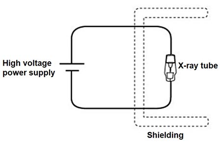
  2. Review Figure 1 below which shows that an X-ray machine is made up of three main parts: a high-voltage power supply that is hooked up to an X-ray tube with shielding around the X-ray tube for safety purposes.
Diagram of a homemade x-ray machine Physics Science Fair Project
Figure 1. The diagram shows the three main parts of a homemade X-ray machine: a high voltage power supply, an X-ray tube, and shielding for safety.

Safety Check
High Voltage Symbol This X-ray machine requires you to hook up and use a high-voltage power supply. Exercise extreme caution when doing so. Accidental contact with high voltage supplying sufficient energy can result in severe injury or death. Furthermore, 20kV of electricity (which is the minimum supplied by the power supply in this project) can easily jump several inches, so do not allow anyone to touch or even come close (less than 8 inches) to the wires, alligator clips, or terminals on the X-ray tube while the power supply is on. A person's body can provide a path for current flow causing tissue damage and heart failure. Other injuries can include burns from the arc generated by the accidental contact.
  • Make sure the wires are properly connected and that you are not operating the power supply close to water or with wet hands.
  • Before plugging in the power supply, make sure that the alligator clips are securely held in place using the electrical tape.
  • Other than the on/off button, do not handle or be closer than 8 inches to the power supply, attached wires, alligator clips, or terminals on the X-ray tube while the power supply is plugged in.
  • Because there is a fire hazard risk related to high voltage wires, make sure that the wires between the power supply terminals and the X-ray terminals are short, hanging in the air, and not close to anything. If there is any metal nearby, such as nails in the floor, uninsulated lead shielding, or another wire, the high voltage may arc through the wires to the metal, possibly melting the insulation on the wires and catching them on fire, along with whatever was being arced to (such as the floor).
Radiation Symbol X-rays are a form of ionizing radiation and can cause permanent tissue damage and illness if you are exposed to too much. Read the Introduction to Radiation & Radiation Safety guide before building and operating this X-ray machine.
  • Never operate the X-ray machine without proper shielding.
    • This includes shielding above the machine if you are on the first floor of a multi-story building with people above you, and shielding below the machine if you are in a building with people on floors below you.
  • Use a Geiger counter to keep track of the radiation levels every time you operate the machine.
  • If the Geiger counter readings outside of the shielding exceed 300 microrem (μRem) per hour, turn the machine off immediately and work on increasing the shielding.
  1. Using alligator clips and 12 gauge (American Wire Gauge, AWG) hookup wire, connect the power supply to the X-ray tube.
    1. Warning: Do not plug in or turn on the power supply until it is all properly connected and the radiation shielding is in place. When working with the high voltage power supply, remember that the output can be deadly if mishandled.
    2. Make sure that you connect the X-ray tube in the right orientation. Because there is a positive end and a negative end to the tube (see Figure 2), connect the power supply so that current flows in the correct direction. Connect the positive output of the power supply to the tip of the tube and the negative end of the power supply to the base pins of the tube as shown in Figure 2.
    3. Note: Size 10 AWG wire will also work for making these connections. The size 10 and 12 AWG are both lower gauge wires, which are thicker, and thus better for higher voltages like the ones outputted by this power supply.
    4. Once the alligator clips are connected to the X-ray tube correctly, wrap electrical tape around the alligator clips and X-ray tube to secure the alligator clips in place.
Photo of the X-ray tube in a homemade X-ray machine Physics Science Fair Project
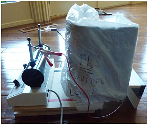
Figure 2. Pay close attention to make sure the alligator clips attach the negative end of the X-ray tube to the negative end of the power supply and the positive end of the X-ray tube to the positive end of the power supply. Once they are in place, secure the alligator clips using electrical tape.
Photo of an X-ray tube connected to a high-voltage power supply to create an X-ray machine Physics Science Fair Project
Figure 3. Connect the X-ray tube and power supply with alligator clips and hookup wire. To contain your setup you may find it easiest to build a wooden platform, like the one shown here, for your X-ray machine.
  1. Next, organize the placement of the power supply and the tube. There are two options:
    1. Option 1: Mount the power supply and X-ray tube on a wooden board as shown in Figure 3.
      1. This option allows the X-ray machine to be easily transported and is the option we will continue to depict in subsequent images.
      2. Mount the power supply using Velcro; secure the X-ray tube by feeding the attached wires though slots in the wooden mount.
    2. Option 2: Hide everything in some sort of container. The exact dimensions of the container depend on the size of the power supply that you use, as well as what you're going to use the X-ray machine for (and thus which parts you need access to often), but it is a neat way to keep everything out of sight and organized.
      1. Caution: In this design, the X-ray tube is more likely to overheat, so make sure to include an opening for a cooling fan.
      2. Dangerouslaboratories.com has an example of an X-ray machine housed in an old toolbox.
  2. Set up the shielding material around the X-ray tube. This step is critical for the safe operation of the X-ray machine. Depending on what material you're using and what you intend to do with the machine, you will have to place shielding in different ways around the tube. Regardless of what you do with the shielding, keep an opening somewhere on the shield for ventilation and cooling. Review the Introduction to Radiation & Radiation Safety document before making decisions about shielding.
    1. Shielding material: Lead and concrete are the two options for materials that are safe to use for shielding.
      1. Lead shielding: Lead is the traditional shielding material. It has a halving thickness of 0.4 inches (refer back to the Information about Radiation and Radiation Safety document for a discussion of what this means). To guarantee safety in this setup, there must be three halving thicknesses around the X-ray tube. This corresponds to a 1.2 inch thick enclosure of lead. Lead is the thinnest reliable shielding material and thus takes up the least amount of room, but it is much more expensive than concrete.
      2. Concrete shielding: You can also use concrete to effectively shield from X-rays. It has a halving thickness of 2.4 inches. To guarantee safety in this setup, there must be three halving thicknesses around the X-ray tube. This corresponds to a 7.2 inch thick enclosure of concrete. If you are using concrete, one of the cheapest means is to buy solid concrete blocks and use them to build a wall or dome around the tube. Make sure the blocks are solid concrete.
    2. Placement of the shielding. Exactly where you place the shielding depends on what you plan to do with the X-ray machine. As shown in Figure 4, the shielding always needs to be placed between the X-ray tube and the power supply, so anyone turning the power supply on and off is not exposed to radiation.
      1. If you want to irradiate objects or organisms in close proximity to the tube, you might want to shield the entire tube, leaving no openings (except the one for ventilation). You can form a concrete igloo around the tube with concrete bricks, or use lead sheets to completely cover the tube. This will keep the X-rays in the area enclosed by the shielding, as long as there is no opening in the material. Be sure to leave enough room for your sample (the object or organisms you want to irradiate) within the shielding enclosure.
      2. If you want to develop images with the X-rays, you should leave an opening in the side or top of the shielding so that a controlled stream of X-rays can escape for the imaging exposure. This opening should never be pointed toward where the machine user might stand or other people might walk by.
      3. If the X-ray machine is on a table, or on the floor of a multi-story building, you must put shielding below the X-ray machine. Similarly, if you are in a multi-story building with people above you, you must put shielding above the X-ray machine.
Completed X-ray machine surrounded on three sides by lead shielding to protect experimenters from radiation Physics Science Fair Project
Figure 4. In this experimental setup the lead shielding (wrapped in plastic for convenience) surrounds the X-ray tube on three sides. An opening in the shielding in the top allows ventilation and prevents overheating. The back is open as this particular machine was designed to be placed against a concrete wall during use. This machine was used in a one-story building, so it did not need shielding above or below it.
  1. Because there is a fire hazard related to high voltage wires, make sure that the wires between the power supply terminals and the X-ray terminals are short, hanging in the air, and not close to anything (including lead shielding, another wire, and any metal in the floor, such as nails). Keep the lead insulated from the wires with some Styrofoam or rubber.
    1. Safety note: High voltage wires will try to arc to metal, and the insulation on the wires will not stop arcing. If there is any metal nearby, such as nails in the floor, uninsulated lead shielding, or another wire, the high voltage may arc through the insulation and to the piece of metal, possibly melting the insulation and catching the wires on fire, along with whatever was being arced to (such as the floor).
  2. Place a fan inside the shielding area so that it can move air around and out of the shield through the ventilation opening. This is very important, since the X-ray tube builds up heat that can interfere with the samples that you may be irradiating and can decrease the life of the tube. The fan will keep the temperature fairly constant and relatively cool.
  3. Find an appropriate place to use the machine. Try to place the machine in the corner of a room, ideally bordered by thick walls that can absorb radiation. Always test and calibrate the X-ray machine before use, as will be covered next in this guide.

Testing the Machine

Now that the machine has been built, you need to make sure that it actually works and that the shielding is sufficient. It is simple and safe to test whether the machine works and also to check for any problems. When using the X-ray machine, it is a good idea to post signs asking others to stay out of the room and to make sure that all pets and young children are also out of the room.
  1. Make sure that the X-ray machine is unplugged and turned off. Turn on the Geiger counter. Record what the normal background radiation reading is.
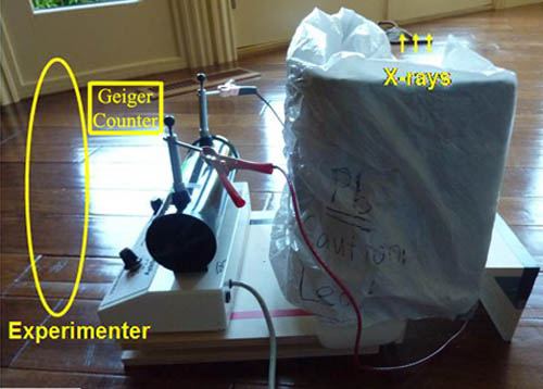
  2. Next you will want to test the radiation reading when the X-ray machine is on from behind the shielding, standing where the "Experimenter" is labeled in Figure 5 below. This will let you make sure that the shielding is sufficient to protect you while you complete the rest of the X-ray machine testing and calibrating steps.
    1. Turn on the fan.
    2. Stand away from the opening in the shielding, plug in the power supply, and turn it to 30,000 volts (30kV). At this point the machine is active and dangerous and is producing X-rays.
      1. Safety note: Other than the on/off button on the power supply, do not handle or be closer than 8 inches to the power supply, attached wires, alligator clips, or terminals on the X-ray tube while the power supply is plugged in. 30kV of electricity can easily jump several inches, and accidental contact could result in severe injury or death.
    3. Standing behind the shielding, where the "Experimenter" is labeled in Figure 5 below, hold the Geiger counter in your hand and take a radiation reading. Any Geiger counter readings above 300 microrem (µRem) per hour outside of the shielding is cause for concern. If you see such a reading, turn the machine off immediately and work on increasing the shielding. Even if the Geiger counter readings are below 300 µRem per hour, you may still want to increase the shielding. It depends on your total exposure. Read "Calibrating the X-ray Machine" below for more details.
  3. When you are done checking your shielding, turn off the power supply and unplug it.
A picture of the X-ray machine setup for testing the shielding for radiation leaks.
Figure 5. To test that your shielding is working, turn on the X-ray machine and stand safely behind the shielding (the place labeled "Experimenter" in this image) with the Geiger counter in your hands.
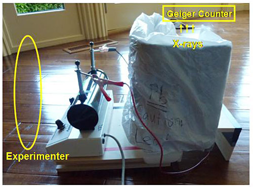
  1. Then, making sure the Geiger counter is still on, place it anywhere from 6 inches to 2 feet from the opening in the machine shielding so that you can read it from a safe vantage point. The idea here is to use the Geiger counter to see whether the machine is outputting X-rays after you turn it back on. You should not hold on to the Geiger counter during this test; instead devise a way to put it down but still read it from behind the shielding as diagramed in Figure 6 below.
Diagram of how to test a homemade x-ray machine Physics Science Fair Project
Figure 6. To test that the X-ray machine is working, place a Geiger Counter a few inches from an opening in the shielding (a shelf above the ventilation opening would work) with the display face of the Geiger counter visible from a safe distance. The experimenter should stand safely behind the shielding, but still be able to read the Geiger counter.
  1. Turn on the fan.
  2. Stand away from the opening in the shielding, plug in the power supply, and turn it to 30kV. At this point, the machine is active and dangerous and is producing X-rays. The Geiger counter should be getting a reading.
    1. Safety note: Other than the on/off button on the power supply, do not handle or be closer than 8 inches to the power supply, attached wires, alligator clips, or terminals on the X-ray tube while the power supply is plugged in.
  3. Observe the reading on the Geiger counter. From the moment that the X-ray machine is turned on, the Geiger counter should have a much higher reading than normal. If it has audio features, it might begin beeping much more than usual. This indicates that the machine is working.
    1. Make sure you have tested what normal background readings are before you turn on the X-ray machine.
    2. If you were to place the Geiger counter right next to the vacuum tube (inside the shielding) while it is running, the counter could max out.
    3. Safety note: Radiation safety is usually thought of in terms of overall dose over time as opposed to an immediate exposure value. However, any Geiger counter readings above 300 microrem (μRem) per hour outside of the shielding is cause for concern. Turn the machine off immediately and work on increasing the shielding.
  4. When you are all done with your X-ray machine project, if you used lead shielding, you should not throw it away. You should recycle it instead. Check with local recycling centers to see if they accept lead.

Troubleshooting After the First Test

During the testing of the machine, you might encounter some problems. Here are a few, along with possible solutions.
  1. Arcing—arcing (the visible jump of electrical current from one component to another) might occur either between the wires and some metal that you have nearby or between the wires themselves. Make sure that the wires are separated from each other and that they aren't near any other metal, including nails in the floor, or lead, if you are using that as shielding. Keep the lead insulated from the wire with some Styrofoam or rubber. Arcing can melt the insulation on the wires and cause it to catch fire, along with anything it is arcing to.
  2. No change in the Geiger counter reading—if the Geiger counter doesn't detect any radiation when the power supply is turned on, there's probably an issue with the wiring between the power supply and the X-ray tube. Turn off the power, unplug the power supply, and check that the polarity of the tube is correct (that it's oriented the right way for current to flow through it) and that the power supply is working correctly. Other possible problems include:
    1. The power supply might be missing a fuse, it might not be plugged in, or it might not be outputting enough voltage.
    2. The X-ray tube itself could be faulty.
    3. The Geiger counter could also be the problem, since it might not be able to detect gamma rays or X-rays.
    4. Check all of these things if you think there is a problem with the machine's ability to produce X-rays.
    5. After you get the X-ray machine working, be sure to re-test the shielding for radiation leaks (as described in the Testing the Machine section above, in step 2).

Calibrating the X-ray Machine

Now that the machine is working, you need to find out how much radiation it can output. You will need to find approximate exposure values at different areas in order to get an idea of your safety and the capability of the machine. Generally, the output energy of the X-rays is correlated directly to the input energy from the power supply. So 1 V of input energy should output 1 eV (electron volt) of X-ray energies. X-ray tubes can generally maintain this 1:1 ratio of input to output energy; the main difference among tubes is in the amount, or intensity, of X-rays produced. The calibration procedure is to determine the intensity of the X-rays in terms of exposure, as measured by a Geiger counter. You will make a table of values that you can refer back to for safety reasons and for radiation calculations later.
  1. Make sure that the machine is turned off and unplugged. Place the Geiger counter 2 feet away from the X-ray tube, in line with the opening in the shielding. Turn on the Geiger counter.
  2. Turn on the fan. Stand away from the opening in the shielding, plug in the power supply, and turn it to 20kV. Observe and record the reading on the Geiger counter.
    1. Safety note: Other than the on/off button on the power supply, do not handle or be closer than 8 inches to the power supply, attached wires, alligator clips, or terminals on the X-ray tube while the power supply is plugged in.
  3. Repeat for various input voltages, such as 20kV, 30kV, 40kV, and 50 kV.
  4. Also repeat for various locations, such as at the power supply location, at your head level when you operate the machine, and at points throughout the area that you work in. Be sure to turn off the machine (i.e., turn off the power supply and unplug it) when you make any changes to the position of the Geiger counter.
  5. After testing you should have a table of values similar to Table 1 below.
Power Supply Voltage Geiger Reading at Each Location
Two Feet from the X-ray Tube Power Supply Head Level Far Corner of Room Right Next to Shielding
20 kV
30 kV
40 kV
50 kV
60 kV
Table 1. During calibration you will make a table, similar to this one, of Geiger readings at various locations around the X-ray machine at different voltages.
  1. The table of values should be sufficient to determine the radiation potential of the machine. If you are irradiating samples, then you can use this procedure to determine their exposure based on distance from the tube. Otherwise, this is useful as a benchmark for safety when using the machine.
  2. Safety notes:
    1. Radiation safety is usually thought of in terms of overall dose as opposed to an immediate exposure value. However, any Geiger counter readings above 300 μRem per hour outside of the shielding is cause for concern. Turn the machine off immediately and work on increasing the shielding.
    2. With radiation the answer is usually the less the better. Here are a couple of facts to keep in mind.
      1. A single chest X-ray or dental X-ray, both of which are considered to be medically safe, exposes a patient to 10 mrem of radiation. Limiting your exposure for a single experiment to 10 mrem would be similar to getting an X-ray.
      2. The international safety standard is 5,000 mrem or less per year. Your annual exposure, both normal and experimental, should fall below the 5,000 mrem level.